Copyright © 2020 Mike Burns
Plumbing
Initially I had not planned to do any of the plumbing, beyond that specifically associated with fitting the kitchen and first floor ensuite. However, early on in the build there was an incident which became known as Showergate, and this led to the first big change of plan.Most houses have a fair bit of plumbing infrastructure in the loft. It depends on your type of system, but for us there was a cold water tank, a header tank for the central heating and some pipes feeding a shower in the second floor bathroom. When you are converting a loft, all of this will get in the way, and if you're planning to continue living in the house while the works are carried out then you will probably want to at least temporarily replace inflexible copper pipes with plastic ones, which can be moved around much more easily.
It quickly became obvious that rather than hire a qualified or indeed skilled plumber, my builder preferred to give the task to one of his general workmen, a chap by the name of Joe, whom I think may have been the one that the term "Have A Go Joe" originally described. This guy started with the shower pipes, a pretty simple task you might think, but the next morning when I got up and tried to turn on the shower - nothing.
I immediately phoned our builder and impressed upon him that this needed to be fixed pronto, as the only other shower in the house at that time was one on the ground floor that was used (and supposed to be kept clean) by our three teenage boys. Sarah and I did not fancy using that one much ! This was a Thursday morning, and we were initially promised that it would be fixed by end of play Friday. However, around Friday lunchtime I received a phone call at work to say that sorry, they wouldn't be able to get it fixed until at least Wednesday the following week. This was a definite non-starter, so I asked my boss nicely if I could take a half-day of annual leave and came home to fix it myself.
Showergate
I discovered that somehow our have-a-go hero had managed to introduce a flexible plastic washer into one of the pipes, and this had been pushed along its
length to the filter on the mixer, hidden inside the bathroom wall, where it had caused a major blockage. Whether this had also been the cause of death of the
pump itself, or he had achieved that separately, I do not know, but I ended up replacing the pump AND cutting a big hole in the bedroom wall behind the shower
(rather than disturb the tiles) to access and clear the blockage.
I got the shower working again that day, and immediately instructed our builder to
take all the plumbing costs out of our quote because I would be doing it myself. He didn't argue.
Original Tanks
The original cold water and header tanks were located slap bang in the middle of the loft space, just about at the foot of where our bed would eventually be. They had to go !
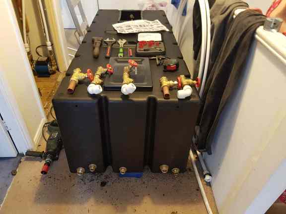
New Cold Water Tank
I prepared the new cold water tank on the landing before lugging it up through the hatch (there were no stairs yet at this point). Holes were cut and the
multiple tank connectors that would be required were attached, in addition to the 22mm ballcock assembly at the other end. Once finished, the house would
have three bathrooms and a further two cloakrooms, so everything needed to be designed for scale. In particular I opted for 28mm feeds for the loft, because
I intended to install a double shower. There's nothing worse than a pathetic shower, and I wanted the flow to be substantial even when both were running.
It's good practice when positioning the outlets to ensure that any feed going via the hot water cylinder is higher than those providing cold service, that way if
the tank should ever run dry then you end up under a cold shower rather than potentially a scalding hot one.
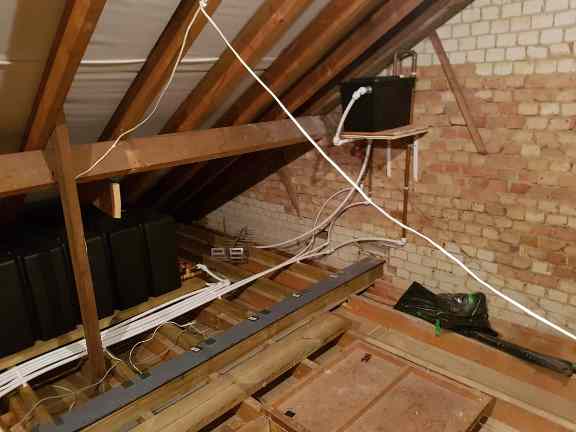
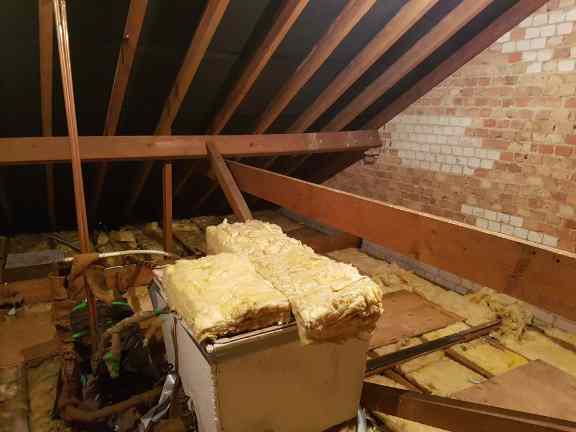
New Tanks Installed
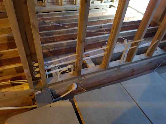
Here you can see the new cold water tank and the central heating header tank in their new positions. You can also see one of the steel I-beams, and the new outer floor joists installed alongside the original slimmer joists holding up the ceilings below. Not yet fitted at this point is the Negative Head pump to serve the loft ensuite. This would be done after the central floor joists were installed. I was very pleased with this installation, it all worked perfectly first time, and was also considerably quieter than the original plumbing.
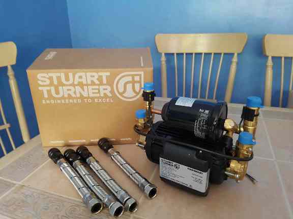
4.5 Bar Negative Head Pump
Again with regard to getting a decent flow out of the intended double shower in the loft ensuite, I splashed out on what might be considered the Rolls-Royce of
domestic twin-impeller pumps. 4.5 Bar basically means "generates lots of pressure". This I eventually installed underneath the small header tank.
The term "head" refers to the height of the water tank above the eventual outlet, and determines how easily the water will flow between the two. The outlets in
the loft ensuite would be above the level of the tank, hence "negative head". A standard pump will not work here because it requires water to start to flow on
its own, which it then detects and turns itself on. A negative head pump has a built-in pressure chamber, which effectively generates this initial flow and
allows the pump to start.
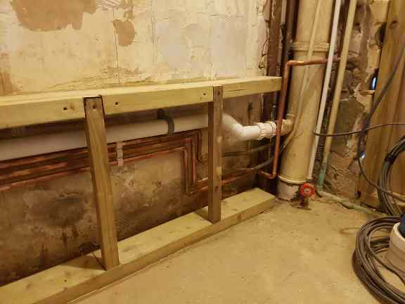
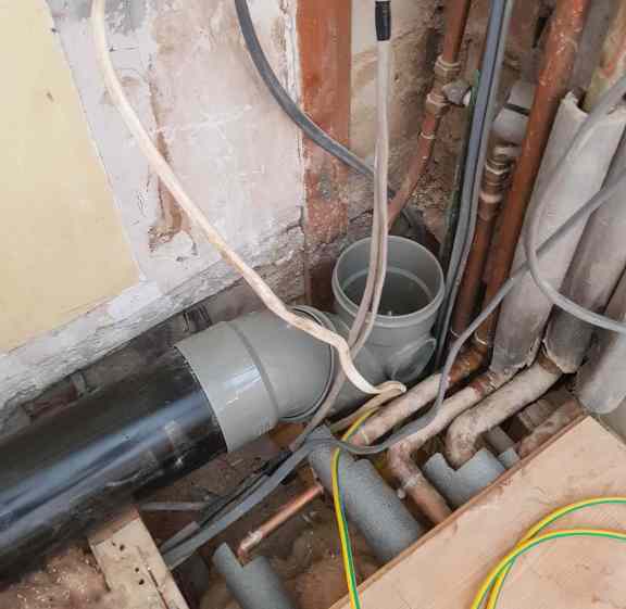
Ground Floor Cloakroom Pipework
As well as the new pipework, you can see here the soil stack in what had been the rear left hand corner of the house. At the very bottom you can see a repair that I had to make, to remove and make good a rather Heath-Robinson (and ultimately slightly leaky - euch !) connection that was there when I bought the house. A previous owner had at some point installled a Ground Floor shower, and due to the levels had been forced to connect to the soil at a point where sections joined, which wasn't really advisable. The awkward profile necessitated a little invention to fix. I ended up heating a piece of CPVC in the oven, moulding it to shape on the pipe and affixing it with solvent cement. For extra mechanical strength and a further seal for good measure (no one ever wants a leaking soil pipe), I then applied epoxy putty around the edges.
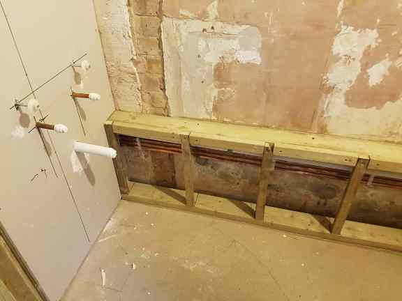
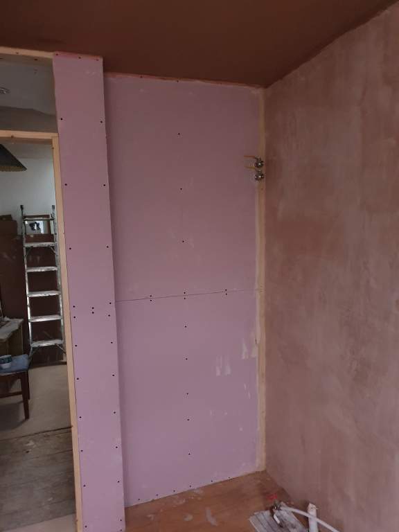
Hand Basin
I had added to the basic studwork put in by our builders a sturdy cross-member to hold the sink bolts, for expediency I also installed this bit of plasterboard so
that I could get on with doing the pipes. You may notice that I changed my mind part way through on the basin that I was originally going to fit, and had
to move the hot cold and drain pipes, hence the patches of filler.
Incidentally, I also built the studwork around the new pipes. I wanted the resulting
box to be very solid but also as compact as possible, and felt it was quicker to just do it rather than try to explain to the builders exactly what I had in
mind. Later on, this box would also contain electrical cabling going up to the loft, a primary earth-bonding cable, and a new flexible gas pipe.
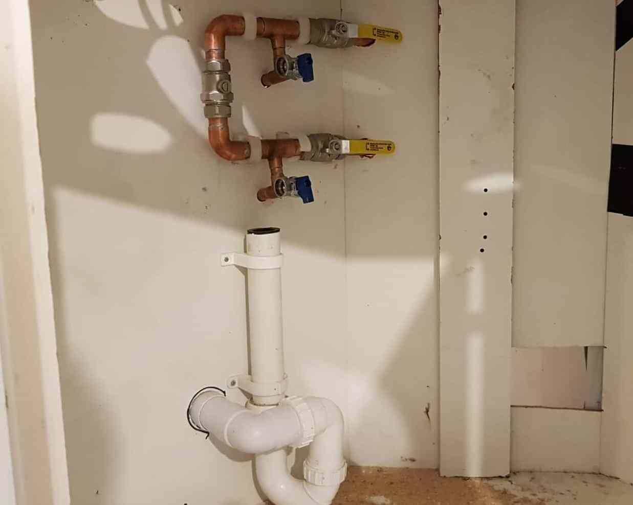
Washing Machine/Dryer Alcove
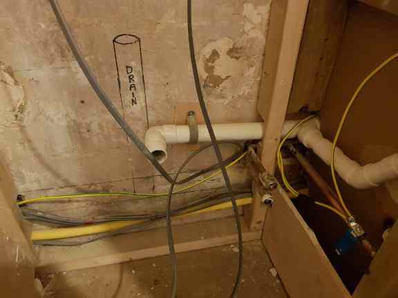
Taken a little later on in the process, this is the alcove on the other side of the stud wall from the basin shown above. You can see the drain and hot/cold supplies for the washing machine, and the pipework for the basin. You can also see the electrical cabling which runs through to the soil stack and then up to the loft. The yellow pipe is flexible gas pipe (branded as Tracpipe). These come through from the cupboard under the stairs to the left, where the meters and fusebox are located. The 10mm yellow/green cable is for primary earth bonding to all the sinks and basins in the house.
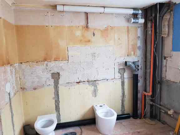
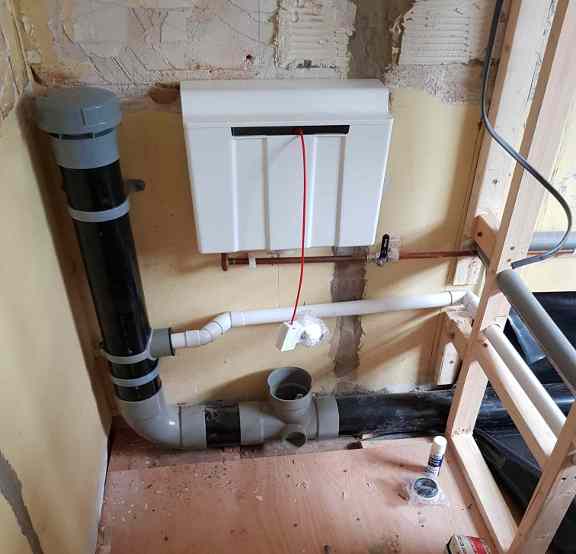
Ground Floor WC
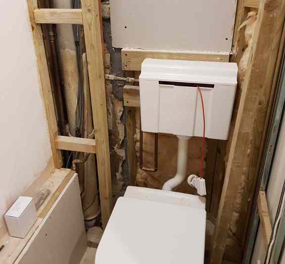
I installed the cistern and connected the toilet pan to the pre-existing sewer connection (separate from the main soil stack to the left), and also built the
surrounding studwork which is only partially complete here. This cloakroom had probably the largest gap of any room in the house between becoming functional
and going into use, which it more or less was here, and actually being finished and decorated, nearly three years later !
Note that the cistern is
offset from the pan, this makes the most of the space and aids access to the pipework on the left hand side, but it would be completely concealed once finished.
Pipework for Ensuite and Radiators
I ran the pipes to serve the loft ensuite (showers, basins, toilet) and also the radiators, two in the bedroom and a towel rail in the bathroom. I would reallly have preferred to use brass compression elbows rather than plastic push-fit ones here, but some of the geometry meant this was just not possible. However, I paid out for Hep20 fittings, which come with a 50 year no-leak guarantee, so if they do ever leak then likely by then it will be an SEP (Somebody Else's Problem) ! I also made sure to always use metal pipe inserts with any fittings on plastic pipes, something which I happen to know that Have-A-Go Joe did not really believe in.
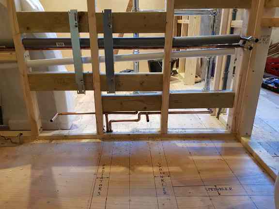
Bedroom Radiators
Here you see me in the process of installing one of the loft bedroom radiators. These would remain isolated and actually lifted off again when the wall was
to be boarded and plastered. So, this meant no live test until it was significantly more difficult to access everything. Happily, when the valves were finally
opened there were no leaks.
The thick orange pipes that you can see are for the fire sprinkler system that Building Regulations required us to install
throughout the whole house. I didn't fit these, we hired a separate specialist company, the main reason being that you have to have a certificate to even buy
the pipe and fittings, and most importantly to sign the installation off and satisfy the Building Inspector.

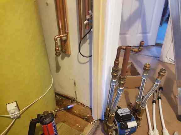
New Hot Water Cylinder
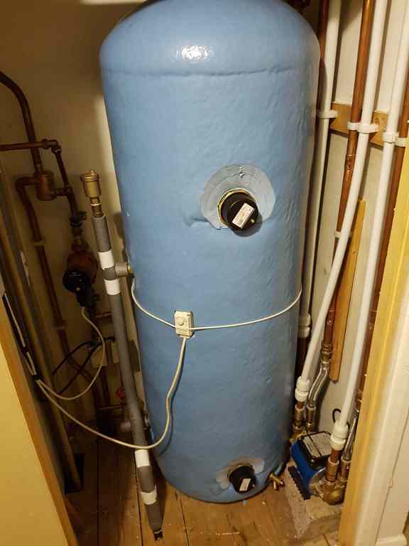
Although unfortunately you can't see it in this picture - it's hidden behind the white cylinder inlet pipe - one feature I love (just because of the name) is
something I installed called an "anti-gravity loop". Whilst this may sound like something that you would expect to find on the Starship Enterprise, in reality
it is just an elongated U-shape of copper pipe which runs from the outlet flange at the top of the cylinder, first downwards almost to the floor before going up
to the pump in the loft. This is necessary because air bubbles tend to appear near the flange, and it prevents them from finding their way up to the pump (air is
less dense than water so always wants to go up, and never down). Instead they should end up in the expansion pipe which goes up to the cold water tank, and thence
out into the atmosphere.
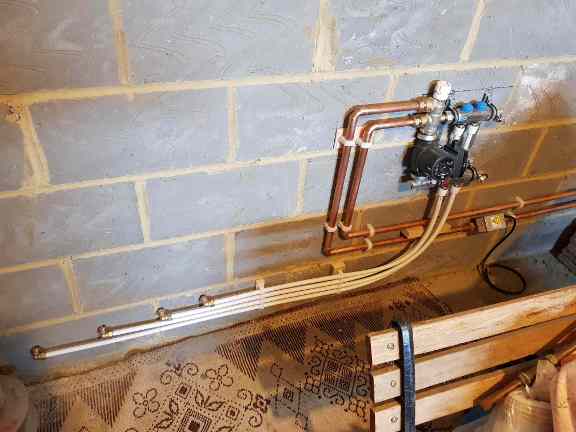
While doing all of this, I also took the opportunity to replace the pump, the motorised valves (two silver boxes under the
red/black pump), and also improve the original simpler and less efficient design utilising a half-cracked ball valve with an Automatic Bypass Valve. This reduces
system noise and stress on the motorised valves when the pump starts up, by automatically allowing the circulating water to bypass them and flow through the cylinder
coil when pressure exceeds a preset level. This became even more important when I further modified the system later to add a separate pump and controls for
underfloor heating on the ground floor.
Underfloor Heating
Here you see the pump, manifold, mixer valve and motorised zone valve during installation of the new underfloor heating system. I have only two underfloor
loops, hence the small four-port manifold (2 out, 2 in). The pipes running out of picture on the right tap into the flow and return from/to the boiler.
It's good practice to mount the motor of the valve above or at the same height as the pipe, because it contains mains voltage, and should there ever be a leak
from the valve itself this ensures that water will not drip onto it. For the same reason, it is mounted to the right of rather than directly underneath the pump
and manifold.
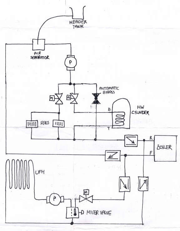
Plumbing Schematic
The installation shown above had to be integrated into the existing system. There are two separate flow paths for the circulating
water. Large (22mm) non-return valves positioned in both the Flow and Return of each path ensure that water pumped by the underfloor
pump does not go round the main central heating circuit, and vice versa.
The diagram is slightly simplified in that it does not include the manifold which splits the underfloor heating circuit section into
two separate circuits.
A motorised zone valve individually controls flow through each of the radiator, hot water and underfloor circuit sections.
A schematic of the associated electrical wiring can be found in the Electrical section.
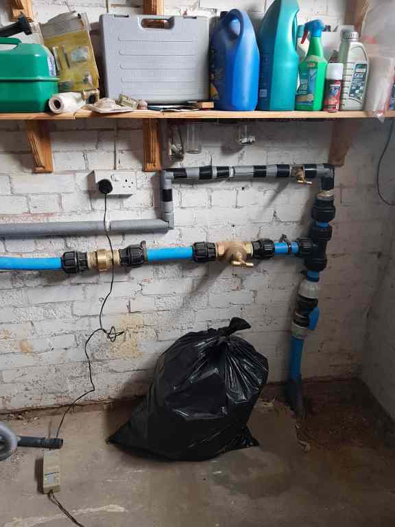
New Mains Water Connection
Here you see the new 50mm mains connection that we had to get installed in the corner of the garage. This was a rather complicated and expensive business. We had
to pay Thames Water to dig up the road outside and mole in a new pipe from the other side of the street, but they will only go as far as your property
boundary. You have to employ your own plumber, who must have suitable formal qualifications, to run the pipe from your boundary into your property and fit a (very
large) non-return valve which you can then connect to.
Although I didn't install the incoming supply or connection for the sprinklers (the blue plastic
50mm pipes), I did fit the 22mm branch coming off the top, which is to replace the orignal 15mm incoming supply pipe at the other side of the house. Slightly
unexpectedly, Thames Water insisted on disconnecting this on the same day the new supply was connected. Fortunately I had planned for the switchover, and was able
to execute this fairly quickly.
In stages, as and when access became optimal, I replaced the whole line up to the cold water tank in the loft with 22mm.
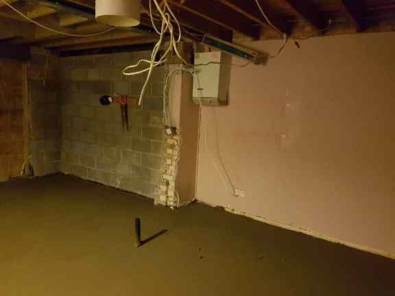
Kitchen Sink Waste Connection
Literally all I had to start with in the new kitchen was a sink waste connection to the sewer line that had been put in by our builders - the black plastic pipe sticking up from the floor. This photo was taken before our builder left the job, and just after the floor had been screeded. At this point you can see that the old boiler is still here. I later had this removed and replaced with a new one in the garage. Boilers I will not touch myself, not because I don't think I could do it - actually I am pretty confident that I safely could - but because it would be illegal without a Gas-Safe qualification.
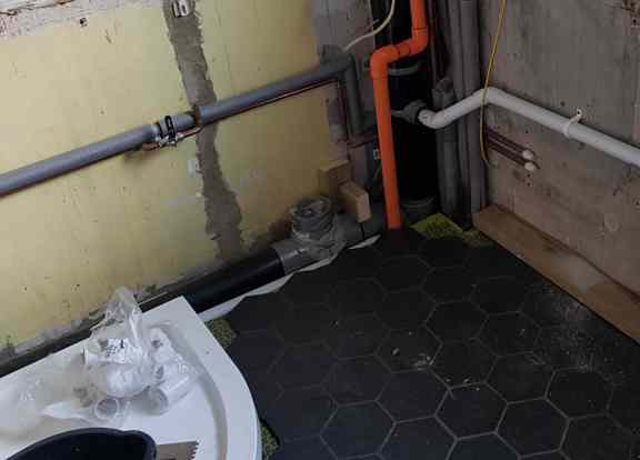
Extractor Vent and Main Water Supply
Here you see the kitchen space after the boiler had been moved, the walls and ceiling boarded and plastered, and the floor tiled. I was able to re-use the hole left by the old boiler vent for a hob extraction pipe. I ran the main incoming cold water supply along the bottom of the back wall, parallel with the orange sprinkler pipe, both from the new 50mm incoming connection in the garage to the other side of the right hand wall. Installed by others for legal reasons, you can also see the new boiler flow, return and gas supply pipes running along the top of the wall, and the new gas spur that would feed the hob. All of this would be hidden behind the kitchen units once fitted.
Water Softener
This view inside the corner floor unit fitted underneath where the old boiler had been shows the connections I installed for the water softener. Softened water cannot be drunk as it contains high levels of sodium, so you have to leave at least one tap in the house unsoftened, and typically this will be at the kitchen sink. It therefore makes most sense plumbing-wise to install your water softener near your kitchen sink. A spur is taken off the incoming supply before the softener to feed the drinking tap, all other water coming into the house goes through the softener. The vertical ball-valve is a bypass allowing you to remove the softener unit if necessary and still maintain your supply, albeit unsoftened. The plastic waste pipe at the bottom drains into the sink waste, and is needed as the water softener periodically "recharges" by flushing through the ion exchange tank with saline water.
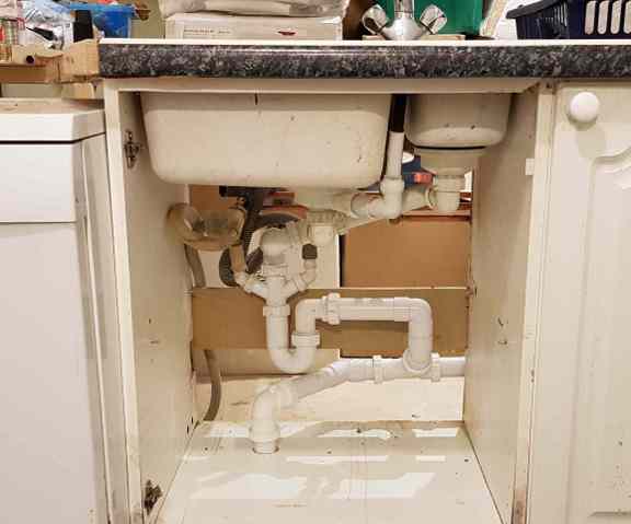
Temporary Kitchen Sink
A new kitchen sink was always going to be required, as the right-hand drainer of the old one would be too close to a join in the worktop. However, as we needed to keep using the kitchen as and while I was installing it, for practical reasons (fitting worksurfaces is a big and difficult job and I couldn't do it all quickly enough in one hit) I initially just loosely placed the old worktops and sink on top of the units. The drain under the sink was therefore done twice - this was iteration 1.
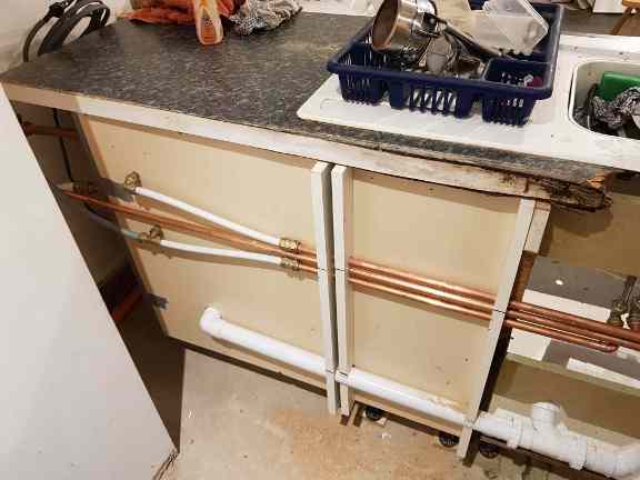
Sink, Dishwasher and Softener Connections
Here you see the old sink and worktop, very damaged by a slow and longstanding leak in the old kitchen, and the pipework that I installed along the back of the floor units that serve the water softener in the cupboard, the sink, and the adjacent dishwasher. There are three copper pipes - hot (from the cylinder upstairs), cold and softened cold. These both come direct from the incoming supply. Water in the cold tank would be softened, hence undrinkable, and you should never drink water from a tank anyway as you would risk contracting Legionnaire's Disease !
A whole new section was slotted into the soil stack with the necessary connections for the new WC branch, and the ensuite shower and basin. Instead of rubber couplings, for greater longevity I opted to use CPVC plastic slip couplings and solvent weld glue. This meant the operation was very time critical - you have about 10 seconds - and I only got one shot at it. It had to be right, in all three spacial dimensions, first time.
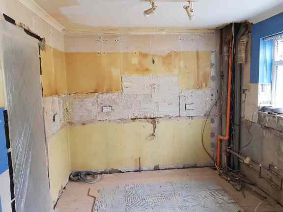
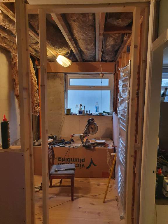
Starting Point - First Floor
This was the starting point for the first floor ensuite and cloakroom, having finished removing the old kitchen. You can see in the right hand corner the
existing soil stack with a single connection for the old kitchen sink. The orange pipe is, again, part of the sprinkler system, this section of which had
already been installed while the kitchen was in situ. It would have been a lot easier to do it once the kitchen was removed, but other dependencies meant
that was not possible.
In the middle of the back wall rising from the floor you can also see the old gas pipe for the hob. By this time this had
already been disconnected and bypassed with a new Tracpipe by my Gas-Safe Engineer, so I was easily able to remove it.
Vent for Cloakroom and Ensuite
Extractor vents would be required for both the new ensuite bathroom and the separate WC, and conveniently I was able to use the existing diamond-drilled
hole for the original kitchen extractor. As there would be two extractors connected to the one pipe, I had to fit two one-way valves in the duct. Note
the use of the silver duct tape - for its actual originally intended use. They are also solvent-welded. Here, in addition to the extractor duct, I have
started to lay out the intended position (in as much as was possible) of the two new WCs and soil pipe sections.
As one of the vents would be
in a bathroom, I also fitted a condensation trap which drains out of another conveniently pre-existing hole in the back wall, this one used to serve the
overflow from the water softener.
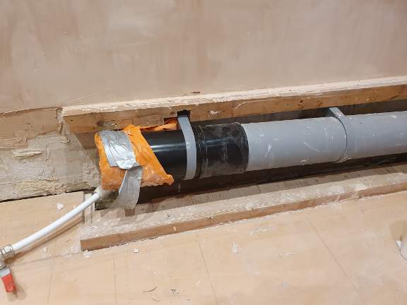
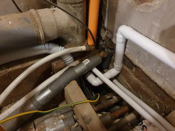
Soil Pipe Branch
Here you see a large section of the soil pipe has been removed between the middle of the first floor and the middle of the ground floor, and the first half of
the new section solvent welded into place. The new branch goes off towards the bottom left of the photo. The new branch needed to have a certain minimum
downward slope to help avoid blockages, and the levels of everything were critical. Due to the levels, the shower waste would actually go down below the level
of the floor to a strap boss connector already fitted in the section unseen below.
While the pipe was removed and access therefore possible, the original
hot and cold supply pipes behind it had to be moved, modified and made ready to connect to the two new hand basins and two toilet cisterns. I also had to work
around the large flow and return pipes from/to the boiler, plus radiator pipes, which are also routed here.
Finally, while all this was exposed, I also
took the opportunity to lag everything with foam pipe insulation, something which previous plumbers had obviously not felt to be that important !
Automatic Air Admittance Valve
I extended the soil stack branch beyond the second WC and upwards, capping it with a clever device called an Air Admittance Valve, also known as a
Durgo. This allows air to be drawn into the soil pipe if a vacuum exists inside, but never lets air, or therefore sewer aromas, out. The purpose of this is to
ensure that the brief vacuum which could be created when the WC nearest the soil pipe flushes does not suck water out of the bowl of the second WC. Instead, air
is admitted to the end of the branch to satisfy any vacuum. This was also a useful point to attach the waste for the cloakroom basin, which is the white CPVC
pipe which runs inside the stud wall to the right of the photo.
You can also see here the cold feed to the cistern, and the hot (foam lagged) and cold
(just below) feeds to the basin taps, which again run inside the stud wall.
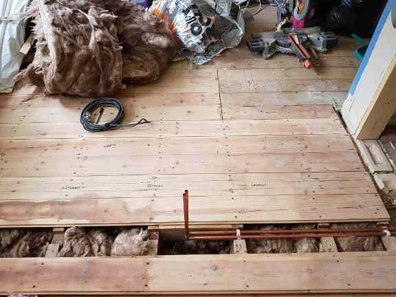
WC and Ensuite Radiator Pipes
Originally there was a radiator at the top of the first flight of stairs, which I removed and capped off before having a doorway knocked
through into the old kitchen space. Once I had cleared the floor and was able to lift the floorboards, I extended these pipes to the position
where the new dividing wall would be, so that they could serve the new radiator and towel rail in the cloakroom and ensuite respectively.
Another handy coincidence meant that there were already slots cut out of the floor joists which dated back to an earlier central heating system,
probably installed when the house was built, and left redundant when I first bought the house 20 years previously and had new central heating
installed. The old pipes were now long-dry, so easily removed, leaving a clear path for these new pipes.
WC and Ensuite Radiators
Here you see the next stage after I built the dividing stud wall, where the radiators were set out and the pipes from the photo above extended to connect to them. You can see the brackets for the cloakroom radiator, and on the other side of the studwork the ensuite towel rail which had been fixed temporarily into position. Towards the right of the picture you can also see the hot, cold and waste connections which would eventually serve the cloakroom hand basin.
Ensuite Shower Tray
The shower tray is now in place, and you can just see the white CPVC drain pipe which connects with the soil pipe below the level of the floor. You can also see the hot and cold connections for the toilet cisterns and the cloakroom basin off to the left of this photo, the CPVC drain for the ensuite basin connecting into a strap boss on the soil pipe, and just below (temporarily capped off) the hot and cold connections for the ensuite basin.
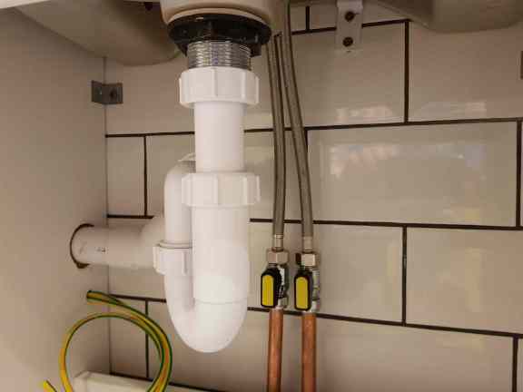
Ensuite Basin
Here, following tiling of the walls, you can see the waste and tap connections for the ensuite basin, fitted inside the vanity unit. The 10mm Green/Yellow cable is the same one seen earlier downstairs, and will be connected to provide primary earth bonding to the copper pipes. The waste runs into the soil pipe as seen in the photo above. I also installed more or less a duplicate of this configuration under the basin in the adjacent cloakroom.

Ensuite Electric Shower
I routed a dedicated 22mm cold water pipe all the way from its own connector on the tank in the loft two floors above, to ensure that the shower pump
is well fed. The pump sits on a shelf above the toilet cistern, which will all be hidden behind a panel.
The last short section of pipe from
the pump to the shower unit itself is 15mm, the size of the connector on the unit.
You can also see here the open duct connection for the
bathroom extractor, the two one-way valves (hidden under duct tape) and the vent pipe running to the extractor in the cloakroom off to the left of this photo.
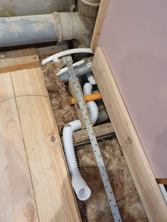
Family Bathroom - Soil Stack Corner
I had increased the size of the family bathroom on the second floor by turning the stairs at the top, allowing me to bring forward the wall by approximately one metre. This
meant that the floorplan completely changed, with a separate shower cubicle also added. This in turn meant modifying or replacing literally all the bathroom plumbing.
Here, part-way through the work in this area, you can see how cramped it gets around the soil stack. Visible are the mains cold supply which comes up the soil stack and routes
through here towards the tank in the loft, the hot and cold feeds from the cylinder/tank respectively, which were split here to head back down the soil stack and across to the
right for the basins in this bathroom and the adjacent bedroom. Also the orange fire sprinkler riser, the solid 32mm PVC drain from the two basins into the soil stack, and the
new flexible 40mm drain from the shower (not in final position). I didn't modify, but did have to work around, the copper central heating flow and return and radiator loop pipes
that also utilise the soil stack to route between floors. In fact it got even more crowded, as an additional 40mm drain had to be routed into the soil pipe from the bath. All had
eventually to be positioned below the level of the new floorboards, as the bath would be freestanding, so there was no other way to hide them. The cramped geometry meant that
flexible plastic pipes were really the only way to fit everything in, and explains (excuses ?) why it was never going to be the prettiest-looking job I have ever done.
Soil Stack Corner Completed
Here you see the same corner once I had finished routing all the pipes and replaced most of the floorboards. The additional flexible drain for the bath is now in place, and the other one for the shower is now below joist level behind the horizontal soil pipe branch. As a little extra timber had been taken out of the joist through which several of these pipes pass, you can see I reinforced it with a (more substantial than it looks here) steel mending plate, screwed and glued at every possible point, and extending along to the next joist as well.
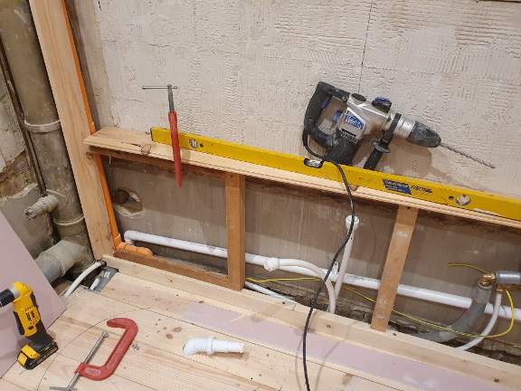
Family Bathroom - Window Wall
As the bath would now be freestanding, pipes could not be routed underneath it as they had been with the previous one. A new box along the back window wall of the bathroom would hide the hot and cold supply pipes to the bathroom basin and the one in the adjacent bedroom, plus the drain pipe from the basins (quite intentionally on a slant), and provide a ledge for the bath taps to be mounted on. You can see the two 22mm capped off plastic pipes ready to connect to the tap once the top ledge was tiled. You may also notice the same yellow/green 10mm primary earth bonding cable that now runs throughout the house, connecting to the hot/cold supply pipes at the point where they transition from plastic to copper.
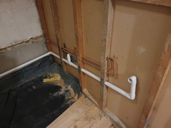
Family Bathroom - Side Wall
A stud wall divides the bathroom from the adjacent Bedroom 3. All the plasterboard was removed along with the old tiles, allowing me to route the hot/cold supplies and drains for both the bathroom and the basin in the bedroom inside the wall. Again, given that the new bath would be freestanding, this was the only way they could be hidden. The studwork here is original, and not as substantial as the stud walls that I have built, so the drain pipe meant holes not far short of the full width. This meant once again I needed to reinforce with steel mending plates.
Family Bathroom - Towel Radiator
The plumbing for the new towel radiator (seen on the right, covered in protective plastic) was completed even before the new floorboards you see here were installed. The pipes for the original bathroom radiator had come up out of the floor, but I re-routed them up inside the stud wall so that they would exit horizontally. The logisitics of removing the rad and refitting it after first plasterboard and then tile had been applied to the wall, and the fact that the floor would also be tiled, meant that I had to route the pipes first out under the landing, where they could still be accessed by lifting the floorboards, and where I also fitted isolating valves, then back into the bathroom and up inside the wall. Once the tiling had been completed and the radiator refitted, the valves could then be opened to allow circulation through it.
Family Bathroom - Shower Cabin
The 22mm pipes from the shower pump in the airing cupboard on the same floor had originally been routed to an over-bath shower. These were re-routed, diverting off above the new
bathroon door inside the ceiling, then down and through the new front wall to the corner position where you see the two lever ball valves. You can also just see bottom right the
shower drain pipe which runs under the floor to the soil pipe in the adjacent corner. The 15mm flexible pipe with the temporary bent pipe and gate valve "tap" is actually what
would eventually feed the new toilet cistern, just off to the right of this photo, but I had used it while plastering to save me going down to the (ground floor kitchen) to get
my water.
Eventually, after tiling, a pre-fabricated shower cabin would be installed in this corner, hiding all the plumbing.
Family Bathroom - WC Soil Pipe
In line with the floor plan change, the new WC would be approximately a foot to the left of where the original one was, which necessitated extending the soil pipe branch to which it
would connect. This I did using a solvent-weld coupler, which is far superior and much longer lasting than a rubber coupler. The orange Sainsburys carrier bag was taped around the
open end until the WC was actually connected in order to prevent sewer aromas escaping. The white 15mm pipe is the same one seen above, my temporary water supply which would also
eventually feed the cistern.
The levels are all-important here - the branch is on a slant to help avoid blockages, so extending it obviously raises the height of the
end. Fortunately the floor level was also to rise, as I laid first plywood then tiles over the new floorbards, so it all worked out nicely.