
Copyright © 2020 Mike Burns
Electrical
Initially I had DEFINITELY not planned to do any of the electrical work. I had been wiring plugs and putting up light fittings since I was 7 years old, and in slightly more recent times, before legislation was put into place, I had done a couple of fuseboxes and even a full rewire on my in-laws' bungalow. However, since 2005 UK law says that you not only have to be a competent person, but you also have to be formally qualified. So, had I done the work then I would still have had to employ a qualified electrician to check and approve it. There didn't seem to be a lot of point.Unfortunately, the electrician provided by our builder did not in all aspects do an excellent job, and also ultimately disappeared without finishing or, crucially, signing off what he had done. Therefore I did end up doing certain works, and did indeed have to employ a different qualified electrician to check and approve it.
That said, it is pretty handy being your own electrician, because so many other jobs also involve having to incorporate or make changes to wiring. If you really didn't want to do any of it, then you would be calling your electrician on a very regular basis. That's going to be costly, and depending upon his responsiveness and availability it could slow down all those other jobs by quite a lot too.
Upgrading the Breaker Panels
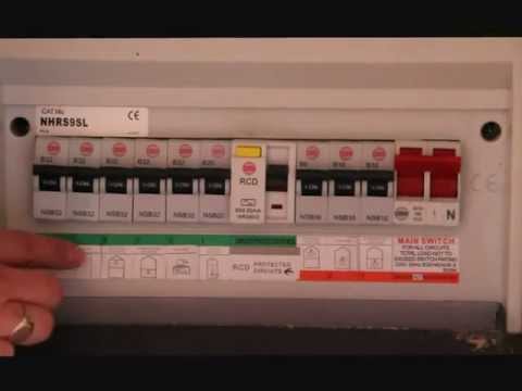
At the time we began our renovations, we had a single split-load panel fitted with individual MCBs. The power circuits were protected by a RCD main switch, but
the lighting circuits were not. This was a fairly common way of doing things when I bought the house (in 1999), and upgraded from the previous truly ancient
wire-cartridge fuse panel that was probably installed when the house was built. However, this configuration, and the fact that the enclosure was made of plastic rather
than metal, meant that it did not meet current electrical standards. The builder's electrician, rather than upgrading the existing fusebox, simply added a new one next
to it which served the new circuits in the loft and rear extension. He didn't even do a particularly good job of that, omitting for example the plastic cable gland that
is supposed to protect the incoming cables from the sharp edges of the metal box. Therefore, after he vanished, I decided to redo his fuse box properly and also
finish the job by upgrading the pre-existing one to the same standard.
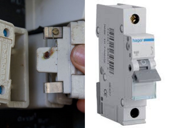
Wire Fuse vs MCB
An old wire fuse works by getting hot and physically melting when too large a current is drawn. By contrast, MCBs (Miniature Circuit Breakers) are effectively a switch which is tripped when too high a current is detected. The advantage of these was that you could reset them with the flick of a switch, rather than having to find and fit a new piece of fuse wire.
RCDs
It's a common misconception that fuses (or MCBs) will protect against electrocution. They will not - their sole purpose is to prevent fire. The very smallest rated fuse in any domestic installation might be 6 Amps, but just a small fraction of that current flowing through the human body will quite easily kill you. The solution to this was the RCD (Residual Current Device), which began to be included in domestic installations in the UK in the 1980s - although other devices with the same purpose did exist earlier than that. A RCD circuit breaker detects earth leakage. Explained simply, if someone is getting an electric shock from some part of the electrical system inside a house then current will be flowing from the Live conductor, through their body to Earth.
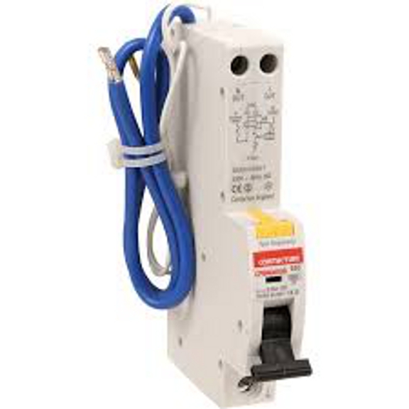
RCBOs
The next stage of the evolution was the RCBO (Residual Circuit Breaker AND Overcurrent). This looks similar to a MCB, and does indeed perform the function of a MCB, but in addition it also performs the function of a RCD. The advantage of this is that only the individual circuit on which the fault has occurred will be shut off, rather than all of the multiple circuits that would previously have been protected by a single RCD main switch.
Main Fuse and Meter Upgrade
All domestic installations are protected by a main fuse. This is the first thing in line, before the meter, breaker panel or anything else, and its purpose is pretty much to protect the network that serves the whole street or wider area, preventing what could otherwise in the case of a short circuit be a fairly big bang ! If all your other cutout measures somehow fail, the main fuse will blow and disconnect your house from the substation. It's owned by the electricity distribution company, and technically even your qualified electrician is not allowed to touch it, although in practice this is a bit of a grey area. The main fuse in my installation was still the original 1960s vintage one, and rated at just 60 Amps.
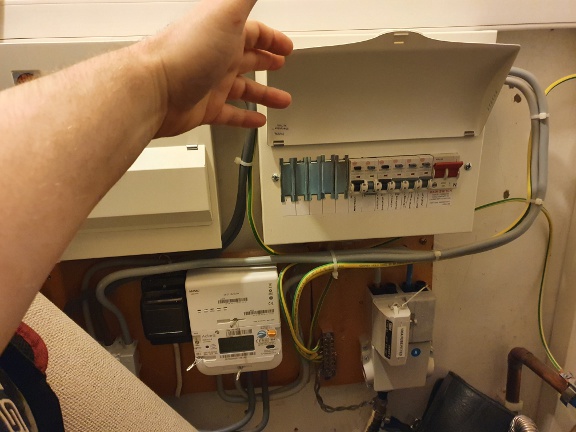
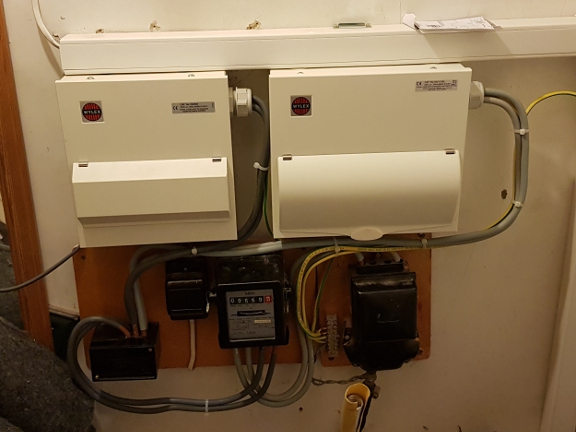
Fortunately, so long as your installation is up to modern standards, which mine now was, the distribution company will come and upgrade your main fuse to 100 Amps for free on request. At about this time I also had the old 1960s-vintage electricity and gas meters replaced with Smart Meters. The meter is owned by the supply company, i.e. the company to whom you pay your bill, which is a different entity to the distribution company, so this was done separately by their subcontractor (also for free). Here you can see the new 100A main fuse (bottom right) and electricity smart meter (bottom centre), along with the RCBOs installed in one of the fuseboxes.
Broken Ring on Main Power Circuit
During the process of upgrading the breaker panels and testing the whole installation, it became apparent that our cowboy builders had left us
yet another little surprise, in the form of a broken ring on the main power circuit. They had messed about with the old sockets in what had been
the ground floor bedroom, breaking the ring, before plasterboarding over them (this being now the kitchen I had also subsequently tiled) so they
could not even be accessed in order to pinpoint and fix the fault.
So what does a broken ring mean ? To explain: a popular wiring topology still used today is known as the "ring main". This means that the
twin+earth cable goes from the breaker, to each outlet in turn, and then back to the breaker, i.e. the cable forms a ring. The reason for this
is that the total load across all the outlets will automatically (thanks Physics !) balance itself over the "to" and "from" cables, meaning
that you can use a smaller gauge (and hence cheaper) cable for a given maximum design load. If the ring is broken, then all the outlets will
still work, because those before the break will be fed by the "to" cable and those after the break by the "from" - but you lose the load
balancing and therefore risk fire, as there may be more than the rated current flowing through either of the two separate cables.
Re-Wiring
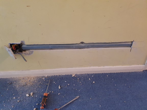
Semi-fortuitously, I was at this time about to start on remodelling the living room, which was to include moving the TV to the opposite wall. This would require a substantial amount of modification to the wiring, including the power. The floorboards were going to be up anyway, so I was able to do the necessary re-wiring of the ring main without substantial additional disruption. Together with wiring under the floorboards of the living room, and in the garage where the wiring was not buried inside the walls anway, the only additional disruption required was to cut one short channel in the wall of the ground floor hallway. It's not the BEST practice to have the cable to a socket run in horizontally, but it's allowed, and as with all cables buried in walls I made sure to cover it with metal conduit, to protect against future accidental drilling.
Updated Wiring Diagram
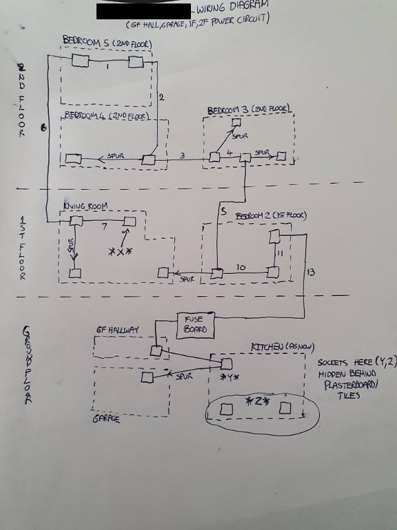
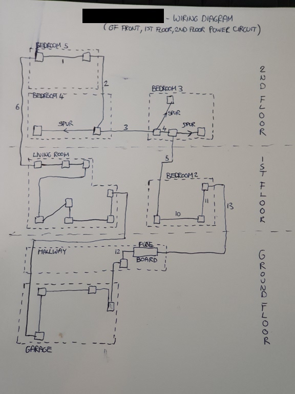
While I was re-wiring this circuit, in addition to adding the outlets I needed for my new AV wall (and some in the garage), I took the opportunity to convert a couple of "spur sockets" (wired as branches off the main ring) to be part of the ring. Here you see the new updated wiring diagram. There are now just 3 spurs, in bedrooms 3 and 4, but every other socket is on the ring.
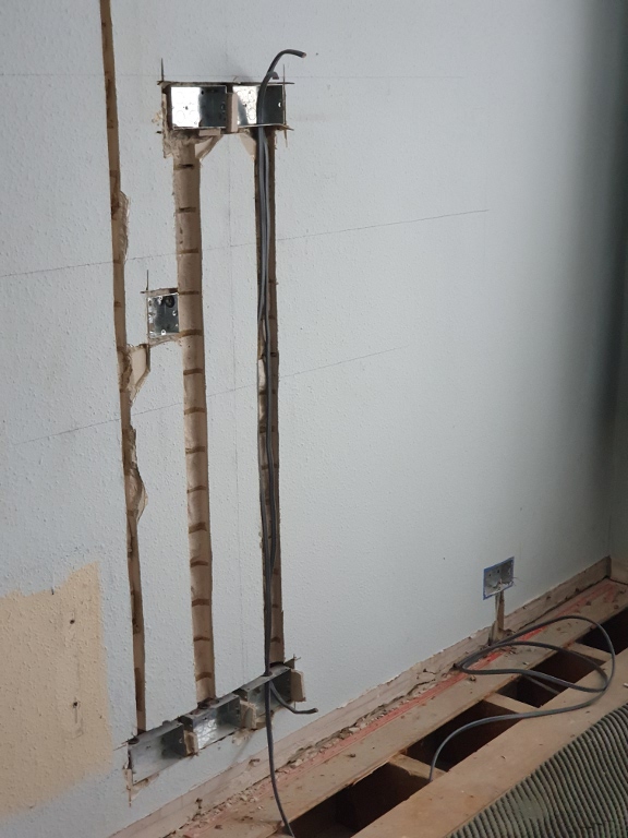
Living Room AV Wall
Here you can see the various backboxes/channels that I cut into the long wall in the living room where the TV was to be located. The rightmost ones are for power, the upper one to be hidden behind the TV and the lower one to be hidden behind a sideboard unit that would eventually sit under the TV and hold the Surround Sound Amplifier, DVR and so on. You can see the power cabling in progress here. The cabling runs down below the floorboards to connect horizontally. The centre channel/backboxes are to carry signal cables between the TV and accessories below - so no wiring to or from the TV would be visible. The narrow leftmost channel is for surround sound speaker cables, which would run up to the ceiling where they would go round the room hidden behind the coving. It was important to ensure a minimum separation between the power and signal cables, particularly the (analog) speaker cables, as if they were too close then EM radiation from the power cables would cause interference and potentially even an annoying 50Hz (the frequency of UK mains electricity) hum on the sound. After all the cables were installed and the power cables covered with protective metal conduit, all the channels would be backfilled with sand/cement mortar and then the whole wall plastered and decorated.
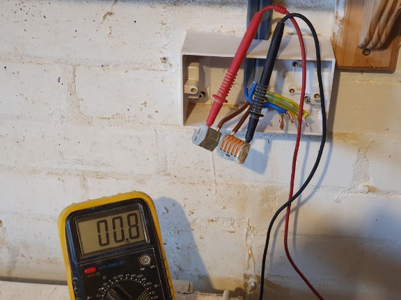
Continuity Checking
Here you see me using a multimeter to check continuity on the three individual conductors of the modified G/1st/2nd floor power circuit, once it was complete and all sockets installed. This socket is one of the ones in the garage, but the checks could be done at any point around the ring. The total resistance around the whole ring should be as low as possible. If it is too high, then some of the connections may not be tight enough, which means they could get hot under load and pose a fire hazard. An open circuit i.e. effectively infinite resistance indicates the "broken ring" problem previously mentioned. This meter is slightly off calibration, and the total resistance was actually about 0.7 Ohms, which given the length of this ring was not bad at all.
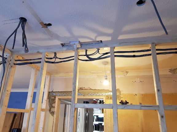
1st Floor Ensuite Cabling
Here you can see some of the wiring for the 1st Floor Ensuite installed during its construction. Given the likely presence of water, which does not mix well with electricity, there are particular rules that must be followed for electrical installations in bathrooms. The cables hanging from the new round holes in the ceiling are for surface-mount LED lights, 4 in total, which had to be IP65 rated (moisture resistant). The power cable to supply the electric shower must be rated to carry at least 40A, and is therefore quite thick and inflexible, plus it is a requirement to fit a suitably rated pullcord switch in series so that power to the shower can be cut off in an emergency.
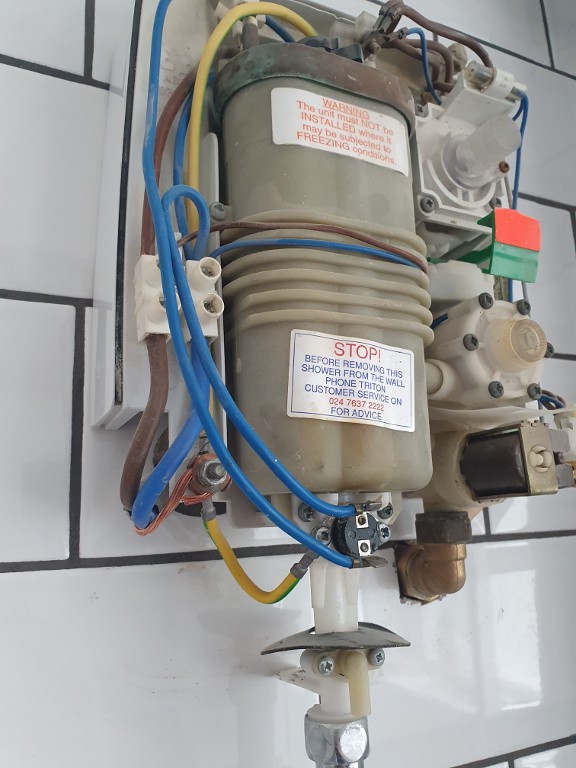
Electric Shower
Here you see the internals of the electric shower fitted in the 1st floor ensuite. The eagle-eyed may notice it is not new, actually this unit was installed for several years in the ground floor shower room before we began our renovations, and I reused it. An electric shower draws a high current (9.5 kW equates to 39.6 Amps) in order to heat the water it uses in real time. If you look at the power conductors coming into the bottom of the white connector centre-left you can see they need to be quite thick. Two of those, together with a correspondingly large earth conductor, bundled together inside an outer protective sheath make for quite a thick, inflexible and indeed expensive cable.
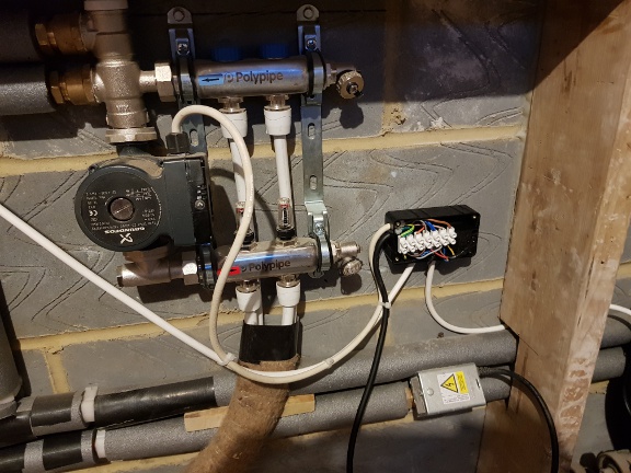
Heating System Electrics
It's quite easy to forget that heating engineers need to be electricians (or bring one with them) too. The valves, pumps and boiler in a typical domestic heating installation all run directly from mains power, and the wiring can be non-trivial. Here you see a junction box that I installed as part of my ground floor underfloor heating system. The pump (centre left) and motorised zone valve (bottom right) plus a control unit (out of shot top left) all needed to be incorporated, and this is just an extension to a larger electrical system, the rest of which is located in the airing cupboard upstairs. My system is more complex than some because the radiators/hot water system and the ground floor underfloor heating are effectively two separate and independent systems controlling and running off one boiler.
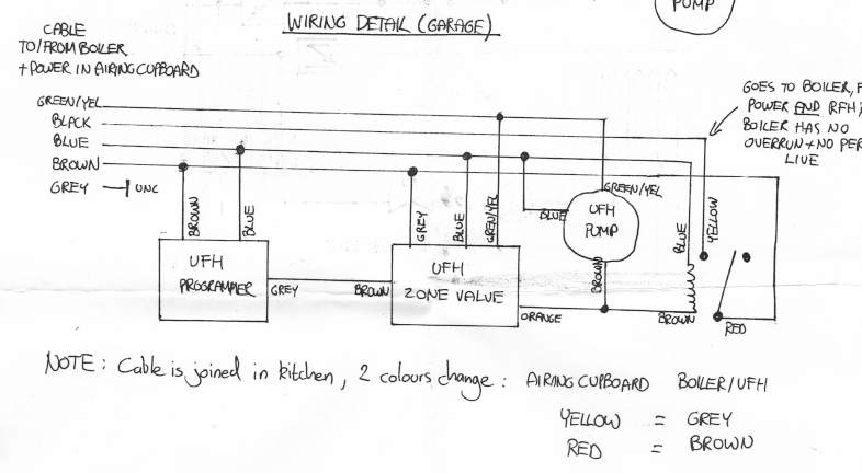
Underfloor Heating Wiring Diagram
This is the wiring diagram for the underfloor heating installation in the garage shown above. The complexity arises in part from the fact that usually the output from a microswitch on a zone valve will directly provide the Call For Heat signal to the boiler and drive the pump. In this installation there are 2 pumps, which need to be driven independently. If the 2 zone valve outputs were simply commoned then either control signal would drive both pumps. Therefore, mains relays are required to isolate them from each other, one for the underfloor heating, shown here, and another for the main central heating system located upstairs in the airing cupboard.